
WIRELESS
ENERGY TRANSFER (FREE ENERGY)
![]() česky
česky
RADIANT ENERGY + COLD ELECTRICITY.
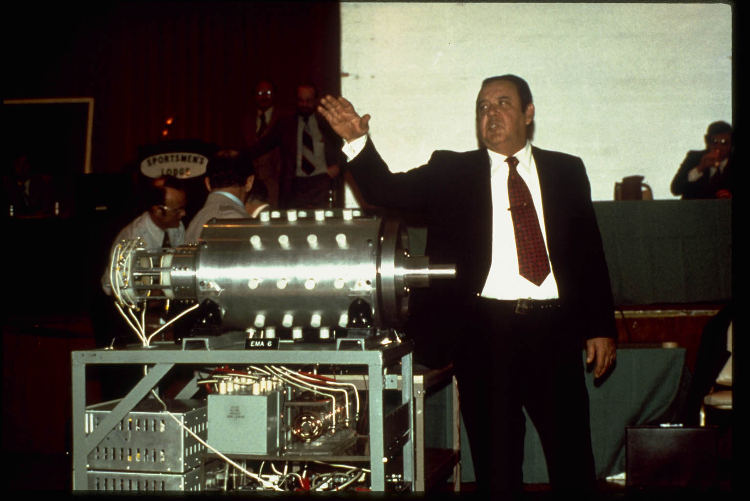
EDWIN VINCENT GRAY´S MOTOR
IS THIS MOTOR RELATIVISTIC?
NIKOLA TESLA TECHNOLOGY
My project is ten times less energy demanding
than classic battery cars and it is supposed the renewable source of energy.
THE MAIN AIM IS TO DEVELOPE COMPUTER CONTROLLED - AUTOS TO CALL THEM BY MOBILE TELEPHONES LIKE TAXI. NO CRASHES. NO PARKING. NO PERSONAL AUTO OWNERSCHIP. THEN THERE IS NO NEED TO HAVE SO MUCH CARS. THE SEGWAY ADVANTAGE - IT COULD TAKE A LITTLE SPACE ON THE ROADS IN CITIES. IT CAN TURN AROUND IN PLACE. THEY COULD "LAY DOWN" ON THE MOTORWAY . It would lay on your back. Head in front. Projection of a road on a computer screen. I THINK THE AUTO WEIGHT SHOULD BE LESS THEN 70 [kg]. NO CHARGING. NO AIR POLLUTION.
The problem I see is that, if in 50 years they drive classic battery cars with a weight of 2 tons, then they will destroy asphalt roads that will not be able to be repaired because there will be no oil! If we have light vehicles, the roads will last a very long time.
https://en.wikipedia.org/wiki/Fatigue_(material)#Stress-life_(S-N)_method
I think it needs to be done to save some oil for plowing the fields.
Motor powered from SPACE !!! Beyond belief...
It was patented in 1975:
http://www.free-energy.ws/pdf/gray3890548.pdf
http://www.free-energy.ws/pdf/gray4595975.pdf It is not an inductive motor!!! It is switching spark gap tube to control motor power.
P.S.DREAMS are really very interesting. 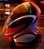
Ask for this design - www.segway.com to get it.
https://www.youtube.com/watch?v=0tiHwzGsotA
The variability of the design can be achieved by various paintings.
It is clear that it will be better to produce 1000 various spare parts than 1,000,000.
free-motor-torrents.rar The files to get.
Problems? Ask for files. cmelak9875@centrum.cz
System of nonlinear differential equations, if it can be solved by finite number of terms of infinite series. Make it fast including control.
The Segway could detect the human weight with the sensor and control it accordingly.
Ask Boston Dynamics' amazing robots Atlas and Handle: https://www.youtube.com/watch?v=uhND7Mvp3f4
An additional air system to control the acceleration of large heights.
More:
To call a small vehicle by a mobile phone, load the package, set where it should go and to whom to send an SMS and then it will go by itself and it didn't have to be recharged.
At present, when a person has 80 [kg], 1600 [kg] is carried in addition to him. In addition, there are a huge number of cases where one would not have to be in the car at all. If at all, then there would be no need to protect him.
Board operating system LINUX english:
https://www.suse.com
http://www.auto.cz/prevodovka-s-plynulou-zmenou-prevodu-cvt-jak-se-k-ni-chovat-aby-vydrzela-99998
My imagination is the 5 [kW] motor 150 [mm] diameter.
IT IS NOT POWER SOURCE FOR INDUCTIVE LOADS.
THE MOTOR PRINCIPLE IS RATHER DIFFERENT.
https://en.wikipedia.org/wiki/Electromagnetism
I would like to introduce fruits of my several years research. I was enthusiastic from the Edwin Gray fuelless engine. My goal was to discover the priciple of this puzzle. A lot of researchers went to wrong blind way. They thought the main source of energy is the tube. The main Edwin Gray patent´s name is: Pulsed Capacitor Discharge Engine. At the first I started to do the computer analyses of this technical object like a classical pulse motor and I have found this interesting thing. There was bad converence when the pulses were fallen. The most of electromagnetic softwares solve so called low frequency electromagnetism, where the wave lenght is much more longer then dimension of the device and influence of an electric field can be neglected. The EG motor is not such device but the RLC response in the begining. The final break through of my research was done by a modal electromagnetic analyses of cores. I obtained very interesting shapes. I have found it is the high frequency transformation phenomenon, which is the main source of energy. To get this phenomenon we need to have an initial magnetic field. We can obtain it by RLC response. Capacitors have intial voltage 3500 V, resintance does looses and when the current goes through the windings, it creates demanded magnetic field. What should we do now? To very quickly interrupte the current. We need interrupt it in time tens of nanosecond, because natural frequences of cores are from 10 to 500 kHz. The question is:How to reach it? The answer is: By small current. It leads to windings with a high number of turns, big resitance and high inductance. This is the reason why Edwin Gray needed high voltage (3500 V) source. The important is: The cores material must not be electrically conductive. I have ideas, how to decrease the voltage. There are two ways: The first one is to have both high permeability and permitivity cores material and second one is to build bigger low RPM motor. Both ways is about to decrease natural frequences of cores. If they are low, we can have longer interruping time, lower voltage, less number of turns with thicker wire in winding and perhaps to use HF bipolar MOS-FET transistor instead controled spark gap. It is my hope.
If you look at the Edwin Gray fuelless engine patent 3,890,548 , there are screws there to tune pulse lengths there to have full initial magnetic field and each coil has separate capacitor. It is due to ensure small quickly interruptable current. Next interesting thing is on the programmer, which is designed the current is interrupted exactly at the same time for two opposite cores and finally there is ring coil around whole engine for distortion of the initial magnetic field to make electromagnetic explosions stable. More can be written about engine air cooling. It is because there is high resistivity in thin wire coils – it heats even it is not the main source of energy.
The heating can come from ferrite cores low resistivity too. This significantly decreases motor effectivity. You should find a good core material.
THEY WROTE, THE MOTOR HAS GOT 30 TIMES
MORE ENERGY THEN INITIAL PULSES NEEDED.
Perhaps by computing optimization you will get more.
CAN THESE MOTORS DRAW ELECTRONS ACCUMULATED IN THE OCEANS?
… the Sun has +++ and the Earth has ---, 200,000,000,000 [V]
Sphere electric charge energy: DATA\energysphere.pdf
I think the oceans have huge electric capacity!!!
And Edwin Gray motors could be discharging them thousands years and
NO Nikola Tesla transmitter is necessary, but I do NOT know.
I have computed Earth water electric energy - 1 [GW] for 3750 years.
Scientific study of the sea water electric properties: https://ulozto.net/!jCbgB0boGkeX/0ii-meissner-tgars-2004-pdf
Some energy computings: DATA\Sun-Earth-Capacitance.xls
I THINK THE TOTAL FREE ENERGY IS THE EARTH ENERGY LIKE
CHARGED SPHERE + ENERGY OF SUN - EARTH CAPACITOR
How does the system behave dynamically?
Solar Wind Control of the Earth´s Electric Field Article:
http://www.sciencemag.org/content/208/4447/979.long
1.Nikola Tesla devised wireless transmitter of energy. The realization of wireless technology would probably demand a construction of many generators in a desert.
https://www.emo.org.tr/ekler/8f44142913d7d06_ek.pdf
They have www.nrel.gov solar cells with efficiency above 44 %. Please, see my ideas below. Renewable energy!
I have got an idea to power self controlled tiny autos 75 kg weight all around the world wirelessly by Nikola Tesla proposals
by solar plants with high efficiency solar cells in 1.5 % Sahara area (to place them, where the Sun is really shining) with 10 GW transmitters
(the last Tesla's design). My imagination are circle solar plants with a diameter 7 km and in the middles the transmitters.
We need oil independent economy.
We need pure nature environment!!!
We need clean buildings facades.
The idea:
Hydropower dams in Russia on the large streams
behind the Ural mountain with Nikola Tesla transmitters.
No problems about telecommunications disturbing.
Huge Solar Power Plant with Tesla Transmitters in Sahara. I have read 1.2 % an area of Sahara is enough for mankind demands. I see this as very good idea, because such power plant would require no maintenance and there would be no refuse from it. There are close to no inhabitants in Sahara.
No fuel, no heat, no water, no turbines, no cooling towers, no pollution!!! World's project - solar power-stations + ocean currents energy with Tesla transmitters floating in the oceans nearly equator. It would be welcomed a mathematical model of Sun and Earth to see if the charging is really needed. Earth charge physics document link.
I have a note for the Nikola Tesla´s wireless energy transmitter. If you have serially connected solar cells DC instead of AC current source, you need not to have an input
transformer even any HV rectifier. You can directly charge the capacitor! It seems to me it is perfectly ecological solution. Floating solar power plants in the oceans.
http://www.reuk.co.uk/40-Percent-Efficiency-PV-Solar-Panels.htm
http://jnaudin.free.fr/html/tmt.htm
http://free-ri.htnet.hr/Branko/07.html
Have a look at the http://www.worldometers.info/ at the side Energy
We can see the mankind demands are around 0.0134 % of solar energy striking our Earth. Spent electrical energy presents conversion to warm, which would meant, there wouldn't problems with warming or refrigeration of the Earth.
Our Earth has a shape of an ellipsoid. It means that the closest distance between an ionosphere and ground is in the near equator area. I see this suitable for charging purposes from this reason. It is known the most of the lighting is nearly the equator.
I hope my solution will have minimal
influence to weather. Follow the link -DREAMS
2. I think that the Edwin Gray engine draws energy for its operation from electric field of the Earth charge - the motor is placed inside this electric field. (They were afraid at that time that the engine cannot run in tunnel.) The engines could have microprocessor control to eliminate variation of atmosphere electric charge. To develope Real Autos Navigated by Galileo Satelite System and Controled by Computers connected to Cameras and Sensors. I believe Edwin Gray engine is much more nature considerate than the combustion engines and it even can be screened by the Faraday cage to remove electromagnetic pollution.
IS IT REALLY REAL??? THESE MOTORS ARE SAID, THEY WORKED!!!
MULTIFERROIC MATERIALS?
http://www.emrs-strasbourg.com/index.php?option=com_content&task=view&Itemid=84&id=225
DC-DC converters HIGH VOLTAGE https://www.xppower.com/product/E-Series?m=E80 ??? Not only one for whole motor.
High Voltage Capacitors: http://www.mouser.com/catalog/supplier/library/AVXHighVoltageCeramic.pdf???
The capacity of capacitors should be just right. Not too small or too big, rather small.
Switching Spark Gaps: https://docs.rs-online.com/b80d/0900766b811705b8.pdf ???
http://www.free-energy.ws/pdf/gray4595975.pdf
Board battery: http://www.lithiumion-batterypack.com/product/24v-15ah-high-capacity-lithium-ion-battery-pack.html ???
Generator to charge the battery to power board computer and peripherial devices: https://www.motocheb.cz/electrosport-stator-vinuti-alternatoru-honda-cbf-1000-06-12?gclid=CjwKCAjwzruGBhBAEiwAUqMR8O1krEdZOPisSIVXiaCTyt03-KnMFYpoH_0wAW5vP9N-A4Hcupg7kBoCsloQAvD_BwE
???
Motor casing: https://www.metals4u.co.uk/aluminium/c1/tube/c22/139.7mm-x-9.5mm-(-5-12-od-x-38-)/p1991
???
We cannot allow to waste free energy!
So called realism in science does matter to understand this technology.
Edwin Gray engine lays on the sharp edge of electromagnetism. It is an electromagnetic jewel.
The main secret:
Electric current from capacitor in the windings creates magnetic field and
after that the current is very quickly interrupted. What does happen, if
material of cores is ferromagnetic electrically non-conductive?
The answer:
Electric-magnetic fields explosion!!!
Electromagnetic waves should go against themselves to achieve repulsion.
The magnetic field can be found not only by electric current in wires.
If you use normal iron, the phenomenon does not arise, because it is overdamped.
Consider the electric-magnetic high frequency response is proceeding inside the electric field of the Earth electric charge which has intenzity
E=66-120 [Vm-1]
and more important is electric charge density
ρ=1-10 [C.km-3]
The energy is transfered through electromagnetic HF response.This motor could not run on the Moon.
I was told that to include relativistic effects into computing is relevant,
that it can be even the main source of energy. I don´n think so.
Imagine the Einstein´s special relativity coefficient:
If we would have not so much good material with relative permeability 100 and relative permitivity 10
then we have the velocity of electromagnetic waves sqrt(1000)=31.62 smaller
then the light velocity in vacuum according the equation:
I think the relativistic effects can be neglected.
But there are these interesting things: Mathematical model in HFSS is not sufficient enough to cover electromagnetic explosions well. I tried to put ferrite permeability and permitivity rather high and free space values and a computing problem occured. I was forced to increase properties of surrounding space to be possible to compute something.There is probably skin relativistic me unknown effect to properly describe the process. It could have great boon for the motor performence maybe even for ecological aspects!!!
? Link above.

There are two main problems to build it:
1) To have permeable electrically non-conductive material for the cores for frequency range from 10 to 500 kHz and with linear behaviour up to magnetic induction 0,4 Tesla, POWER FERRITE
I see the suitable core material 3C95 (3C97) MnZn ferrite:
Plates to cut demanded profiles by water. http://www.awac.cz http://www.flowwaterjet.com
Maybe the MnZn ferrite electric resistivity could be increased to magnify
motor performance. There is a lot of articles about it on Internet.
MnZn ferrites have a high value of permitivity too.
3F36 ??? https://elnamagnetics.com/wp-content/uploads/library/Ferroxcube-Materials/3F36_Material_Specification.pdf
https://dxtmagnetics.com/product/ferrite-block-120-120-38-3/
2) To quickly interrupt current during 1-10 nanoseconds
THE EDWIN GRAY ENGINE PRINCIPLE:
THIS IS A HIGH FREQUENCY ELECTROMAGNETIC DEVICE
(It means, that wave length is shorter then dimensions of the device.)
IT IS NOT AN INDUCTIVE MOTOR
a) THE ELECTRIC CIRCUIT IS NOT THE MAIN SOURCE OF ENERGY
b) ELECTROMAGNET CORES HAVE NATURAL FREQUENCE GIVEN
BY THEIR GEOMETRY, PERMITIVITY AND PERMEABILITY.
f) ACCORDING TO MINE OPINION, EDWIN GRAY HAD PROPOSED
CONTROLLED SPARK GAP TUBE, NOT CONVERSION ONE.
g) RADIANT ENERGY IS ALSO ENERGY TRANSFERED THROUGH ELECTROMAGNETIC WAVES.
h) EXCITED ELECTROMAGNETIC WAVES ARE THE GATE FOR ENERGY FORM TRANSFORMATION
i) I CALL IT A TAMED TESLA COIL
j) IT WORKS ON THE ELECTROMAGNETIC TRANSFORMATION PRINCIPLE
k) I SUPPOSE FULL
2D MAXWELL'S EQUATIONS ARE
VALID
http://www.cheniere.org/misc/gray.htm
Both devices could be CAE optimized.
My imagination is the 5 [kW] motor 150 [mm] diameter.
There is effort to power cars by hydrogen cells, but charging these requires a huge nuclear power plant complex inside a country. I think that from the ecological point of view it would be better to have SOLAR power plants with TESLA TRANSMITERS in Sahara.
IF YOU TAKE A LOOK AT APPROPRIATE PAGES ON THE INTERNET, THESE ENGINES WERE ALREADY PRODUCED IN THE USA DURING THE 1970’s, BUT THEY WERE BANNED FOR VARIOUS REASONS. ONE OF THE REASONS WAS THAT IT DID NOT RECEIVE PUBLIC UNDERSTANDING. ENGINES ARE SAID TO PRODUCE 30 TIMES MORE ENERGY THAN REQUIRED FOR INITIATORY PULSES. IF IT DID NOT WORK, IT WOULD NOT BEEN PATENTED. WITH HIS INVENTION EDWIN GRAY TIED INTO NIKOLA TESLA’S INVENTION.
The current pulse from capacitor C1 makes RLC oscilate. Durring this oscilation the energy from V2 is pumped through capacitor C3. In real the oscilations are three dimensional.
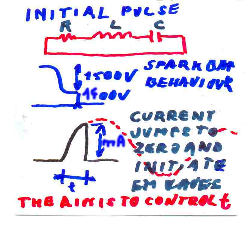
Now I have found this: (figure Q). If you discharge capacitor into inductance, RLC circuit is created with spark. If it is connected with wire for long time the current runs in damped sine (or aperiodic) function. The capacitor would be charged periodically positive and negative. If the voltage on capacitor is zero, we have maximal current in the RLC system (and maximal magnetic field). The tungsten spark gap behaves in this way: It switches on, if voltage is for example above 3500 V and switches off if voltage is less then 500 V (I have this experience). FourierOfPulses.xls I think it is possible to get with tungsten spark gap 80 % of theoretical maximal current and then current jumps to zero - is interrupted. This jump is very important to start electromagnetic waves in the system. The disadvantage of spark gap is, it discharges capacitor too much. We need to control current maximum by impulse duration. I thought it is good to have small inductance and big capacitance. Now I do not think so. It should be done in such way to create full magnetic field. Thomson formula result should show the times. So that inductance (wire thickness and number of turns) and capacitance should be optimal. Now I do not think the thick wire is the best. Electromagnetic waves are sponged upon surrounding electrostatic field. It is so called back E.M.F. phenomenon. This is the main efect. The electromagnetic waves are the gate for transformation of energy forms.
I think that, I already know, why my experiment has not brought, what it is expected. The problem is the core material. Namely the current in RLC circuit is necessary to switch to zero during 10 nanoseconds in time, where's the perpendicular dashed line. It can be seen in the figure current - carrying 10-100 [mA] at the time roughly 2-3 miliseconds after start of transitional response. If the RLC has nonzero resistance, it is not valid the maximum current in the circuit is when a capacitor has zero voltage. It entails that the tungsten spark gap is not suitable for this purpose (It switched off even at the time, when capacitor has negative voltage), when according to calculation is in the circuit the current is practically 0 amperes. Initial voltage on capacitor is 3500 volts.
I thought IGBT transistors are suitable for this purpose but now I do not think so. The device must work with small currents.
 CAD
model: EdwinGrayOrig.igs
Ansys2Dmodel
MoreAnsys2Dstudy
CAD
model: EdwinGrayOrig.igs
Ansys2Dmodel
MoreAnsys2Dstudy
Magnetic field XY Electric field Z relevant boundary condition is missing
- electric field on the surface of the casing ProposalDouble02a.jpg
The cores of the electromagnets should be close to the inner surface of the case - just right.
Cross sections of windings should be small maximally surounded by ferrite.
MORE-PROPOSAL DSC2188prop ANSYS10-2D-DSC2188.MAC.txt MODEL04.MAC.txt
PTC Pro/Engineer 2001
I think, that electrons go through the cylindrical gray casing and through the blue three triple segments from the shaft. Yellow parts are electrically nonconductive with an varying electric field.
What about to use some material with higher permitivity for them?
The original motor had pairs of two cores. One smaller then second one.
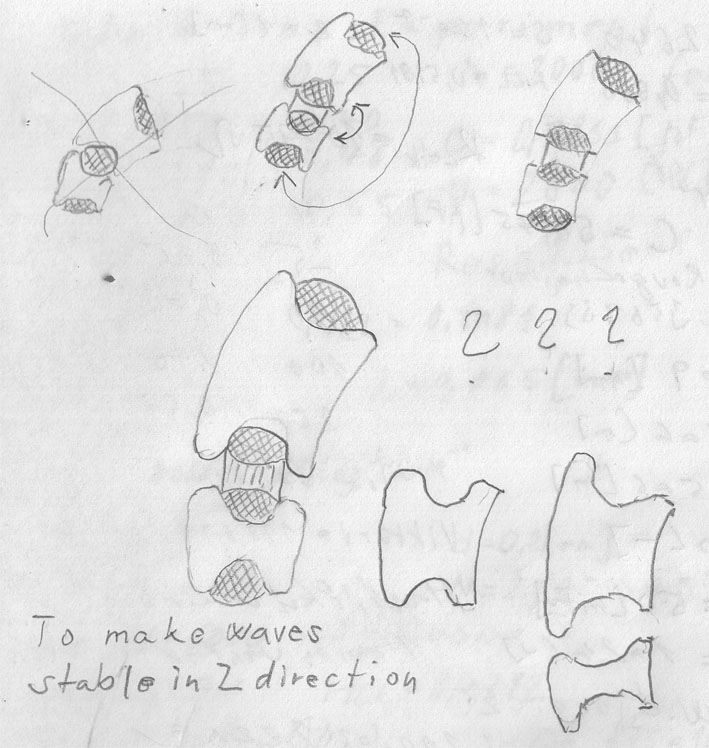
I think, the target was to achieve 2D modal profile extruded in Z direction (no sinusoidal waves). The remain problems are about the winding configuration, how to properly excite the right modes.
See the book links below.
Material of electromagnet cores is permeable electrically nonconductive. I do not know what material would be the most suiable. Indeed, it is incredible, that those conversions happen there: (electrostatic->magnetic->mechanical work). Since iron is electrically conductive a problem with it occurs. I believe in high frequency non-conductive magnetically soft special materials, like amorphous iron is, because it is permeable, electrically non-conductive and it has good high frequency electromagnetic performance. The problem can be to have demanded shapes producing technology. Magnetic part of electromagnetic waves is transformed to mechanical work and waves are refilled from surrounding electrostatic field.
I admire the genius that inventor. At that time they didn't have computers yet !
The shapes are proposed to be possible easily mount them to rotor and stator. There are three cores on the rotor and twelve on the stator. If windings of three cores on the rotor are connected in parallel, it is needed no brush ring on the shaft! It is electrically connected through bearings. I suppose to use four (4) RF MOSFET MOTOROLA (MRF154) HIGH FREQUENCY TRANZISTORS (to have current fall time less then 10 microseconds) transistor modules, angle sensor on the shaft and microprocesor control.
I have been thinking about a cheap sensor to measure torque. I have found this handy solution. There are strong electromagnetic waves inside engine. What about to take a piece of this energy by antenna and well tunned LC circuit, rectified by fast diode, filtered and stabilized to power microcontroler, which would transfer signal from well positioned tensometer to serial digital pulses for infra LED taken out the shaft axially. Then it does not matter if LED is spinning. There would be all device on the rotor. No battery is needed.
As you can see the cores can be placed inside duralumin tube -
it is well sreened to produce close to no electromagnetic polution.
The case even must be electrically conductive!!!
I think, the motor behaves like space resistor - it sucks surrounding electrons.
It could be by chromium coated to avoid oxidation.
Should we make the cores without juts for fixation and glue them to excite better the desirable working modes ?
My idea to simplify the problem is to run 2D modal analyses and to get the mode below and to use this natural
frequency for running 3D harmonic analysis to see the cores ends behaviour. It is solvable by ANSYS 10.
You can also make Fourier serie of pulses FourierSerieOfPulses.xls and then to run 3D harmonic analyses with higher frequency parts and then these component resuslts add up together in the ANSYS10. Low frequency modes can be neclegted - they have small influence to the results (They are not solvable.) FOUPULS04.MAC.txt + Ansys10.0-OriginToInterfaceTHERE WAS NEED HELP TO REPAIR ROUTINES FOR READING IMAGINARY PARTS OF THE BINARY RESULTS FILES RMG EXTENSION ANSYS 10.0 . THE ERROR IS NOT IN LIBRARIES binlib.lib and binlib.dll ,BUT SOMEWHERE IN FORTRAN CODE. THIS INTERFACE COULD BRING WONDERFUL COMPUTING FOR MANY PEOPLE. It can be seen the problem can be solved by modification of the RedRd.F file.
c ***** result set found - read load set headers *****
c ***** solution to read imaginary parts from complex results to add
kcmplx into code *****10
ResRdSolBegin = 0 LocSolHeaderL = largeIntGet(iResIndex(nSets+kcmplx), x iResIndex(nSets+kcmplx+MaxResult))You should use in torrents package:
free-motor-torrents.rar The files to get.
Problems? Ask for files. cmelak9875@centrum.cz
edwingraymotor-fourier11032016-rar
edwingraymotor-fourier27052016-rar
Outline:
Edwin Gray EMA motor - FEM_ANSYS10.0SP1_3Dmodels_for_harmonic_Fourier.rar
FEM_ANSYS10.0A_3Dmodels_for_harmonic_Fourier.rar
visual-studio-2008-professional-edition-x86-and-x64
intel-visual-fortran-compiler-v11-1-067-tbe-rar readme.txt
I recommend:
Visual Studio 2008 C++ Professional Windows/XP FORTRAN CAN BE INTEGRATED IN THE VISUAL STUDIO 2008
Visual Intel Fortran 11.1 compiler Windows/XP readme.txt
We can
use triangular periodic function instead of the RLC response function because
the computing can be less complicated. We should use the pulses length
to have harmonic function frequency N-times lower then the natural frequency of
cores. I could estimate the N around twenty, but I do not know. The zero current
level
delay between pulses should be chosen to get good damping nearly zero close the
next pulse. The most
interesting is the electromagnetic behaviour in the short time
after pulses. There
is need to achieve the exciting of the right working waves modes.
___________________________________________________________________________________________________________
HFSS 13 is usable to solve this - we can run initial RLC response like quasi-static analyses.
If you suppose an infinity capacitance capacitor and zero winding resistivity , you can have
linear current function and then to jump it to zero. You should run full transient analyses.
I see as a better way is to use Broadband Pulse - these are higher frequences of the Fourier
serie added together. You can check it with my FourierSerieOfPulses.xls
You can run modal analyses and then to adjust broadband pulse frequencies parameters.
An initial magnetic field should fit to the working mode of the modal analysis.
I think, this is the best me known software to solve Edwin Gray motor electromagnetic processes.
_______________________________________________________________________________________________
YOU CAN USE COARSE TETRAHEDRAL MESH AND TO SOLVE IT BY
DISCONTINUOS GALERKIN TRANSIENT WITH INITIAL MAGNETIC FIELD http://www.nudg.org

I think you should start with this:
Mathworks MATLAB R2007b: torrent
Microsoft Visual C++ 2008: torrent
You will need to compute the initial conditions through a Poisson solve and you can then use that as the initial conditions in a time-domain solvers. You can finds most of the pieces to modify at www.nudg.org -- you can find both Matlab and C++ codes that solvers Maxwell's equations and the Poisson equation. If this is not what you need, you will need to modify the solvers provided but that should - hopefully - not be too bad.
You should do computer analyses before you build prototype!!!
To quickly interrupte current in winding tens of [nanoseconds] and start electromagnetic waves in cores, the current mustn't reach big values. It is solved by thin wire in winding and big number of turns. Because then the winding has big inductance and resistance, so we need high voltage to get demanded initial magnetic field. We have at the first the RLC response. I think IGBT semicondictors are not suitable for it. It has too long fall time (tens of nanoseconds). They are suitable for big currents. The current must be small.
If it isn't just even better to use the Gray vacuum switching tube.
These are contours of the electric field in Gray's tube. My opinion is, it is a controlled spark gap.
I think, the reason of cylinder inside tube (probably carbon) with bigger diameter connected to the rod was used to decrease gradient of voltage.
I see this Edwin Gray's patent of THE TUBE as very confusing!
Feel free to send me any comments, ideas or suggestions
that you would like to share and
I will be happy to discuss the matter further.
Michal Martinů, Eng.
DREAMS FDTD-test
MIDI-MUSIC
![]() česky
česky
Researcher from the Czech Republic The rarity: The steam engine model in CAD ProEng2001:
Pascal - Delphi - Numerical Library: NUMERIC-LIB-PASCAL.rar
I have rewritten some routines from it to C - C-routines.rar
Complex Matrixes in C - routines.
Eternity puzzle: DATA\eternity00001.c DATA\eternity00002.c Turbo C 2.01
